
Most beginners are confused by the usage of two or more seven segment displays; here is an instructable demonstrating the implementation of the same using a microcontroller.
This is achievable because of the rapid switching speed of the LED and the microcontroller.
Components/Materials Needed:
- Arduino UNO R3
- Breadboard
- 2 pieces of 7 Segment Display
- 2 pieces of 220 ohms resistors
- Jumper Wires
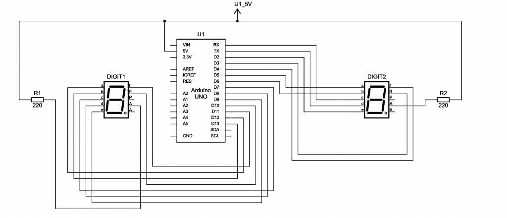
Schematic Diagram of a Circuit
Sample Code
// 7 Segment Display Activity (0 to 99)
// By: Isaiah B. Eje
// Declare Variables
int a = 12;
int b = 13;
int c = 7;
int d = 8;
int e = 9 ;
int f = 11 ;
int g = 10;
int a2 = 5;
int b2 = 6;
int c2 = 0;
int d2 = 1;
int e2 = 2 ;
int f2 = 4 ;
int g2 = 3;
int wait = 600;
// Setup
void setup() {
//initialize pinMode from the two 7 segment display
pinMode(a,OUTPUT);
pinMode(b,OUTPUT);
pinMode(c,OUTPUT);
pinMode(d,OUTPUT);
pinMode(e,OUTPUT);
pinMode(f,OUTPUT);
pinMode(g,OUTPUT);
pinMode(a2,OUTPUT);
pinMode(b2,OUTPUT);
pinMode(c2,OUTPUT);
pinMode(d2,OUTPUT);
pinMode(e2,OUTPUT);
pinMode(f2,OUTPUT);
pinMode(g2,OUTPUT);
}
// Define of the method to control the first display.
void display (int a, int b, int c, int d, int e, int f, int g)
{
// Define for each segment one pin.
digitalWrite (12,a);
digitalWrite (13,b);
digitalWrite (7,c);
digitalWrite (8,d);
digitalWrite (9,e);
digitalWrite (11,f);
digitalWrite (10,g);
}
// Define of the method to control the second display.
void display2 (int a, int b, int c, int d, int e, int f, int g)
{
digitalWrite (5,a);
digitalWrite (6,b);
digitalWrite (0,c);
digitalWrite (1,d);
digitalWrite (2,e);
digitalWrite (4,f);
digitalWrite (3,g);
}
// Define of the count down method for the second display
void display2play ()
{
// Specify as 0 the segments that we want to power on
display2 (1,0,0,1,1,1,1); delay(wait); // 1
display2 (0,0,1,0,0,1,0); delay(wait); // 2
display2 (0,0,0,0,1,1,0); delay(wait); // 3
display2 (1,0,0,1,1,0,0); delay(wait); // 4
display2 (0,1,0,0,1,0,0); delay(wait); // 5
display2 (0,1,0,0,0,0,0); delay(wait); // 6
display2 (0,0,0,1,1,1,1); delay(wait); // 7
display2 (0,0,0,0,0,0,0); delay(wait); // 8
display2 (0,0,0,0,1,0,0); delay(wait); // 9
display2 (0,0,0,0,0,0,1); // 0
}
//Defintion of the loop
void loop() {
//For each number of the first display, the second one goes from 0 to 9
//By this way we can obtain a 0 to 99 counter loop
display (0,0,0,0,0,0,1);
delay(wait);
display2play();
display (1,0,0,1,1,1,1);
delay(wait);
display2play();
display (0,0,1,0,0,1,0);
delay(wait);
display2play();
display (0,0,0,0,1,1,0);
delay(wait);
display2play();
display (1,0,0,1,1,0,0);
delay(wait);
display2play();
display (0,1,0,0,1,0,0);
delay(wait);
display2play();
display (0,1,0,0,0,0,0);
delay(wait);
display2play();
display (0,0,0,1,1,1,1);
delay(wait);
display2play();
display (0,0,0,0,0,0,0);
delay(wait);
display2play();
display (0,0,0,1,1,0,0);
delay(wait);
display2play();
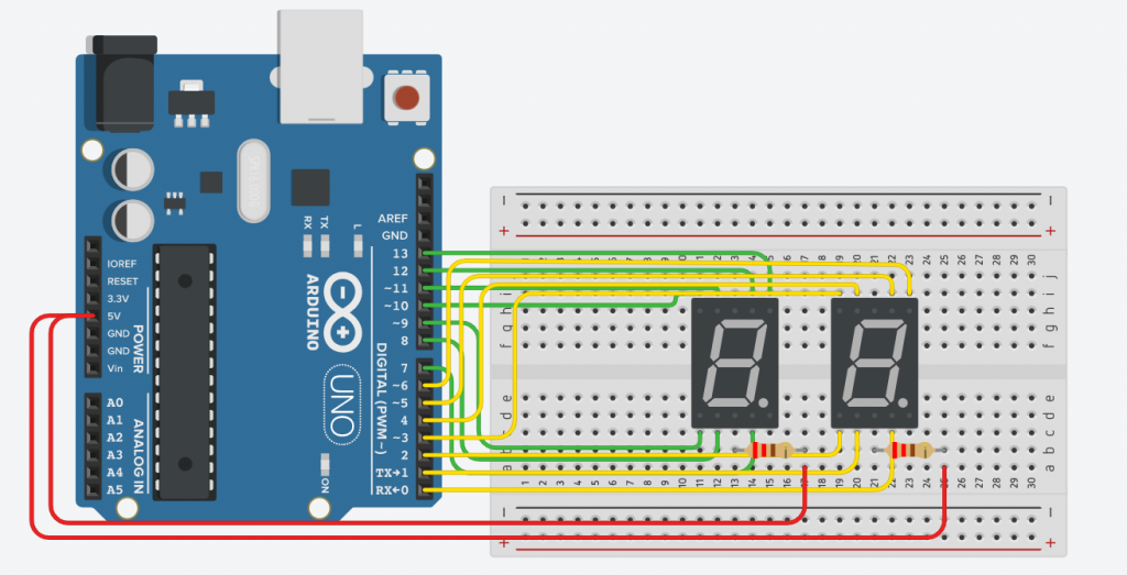
}sample Simulation using Tinkercad
I hope you can enjoy it!