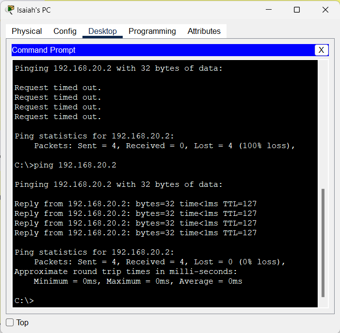
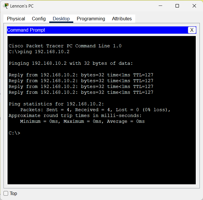
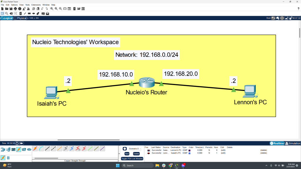
A router and two Computers are utilized in this network. A copper straight-through connection connects computers to routers. To test network connectivity after building the network, a basic PDU is transmitted from Isaiah’s PC to Lennon’s PC. The network simulation state is good. It is clear from this network that the router handles data transfers between numerous devices.
Procedure:
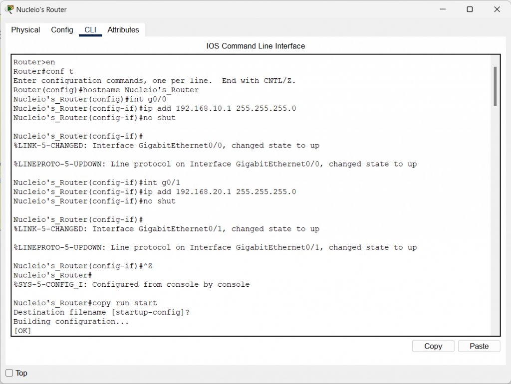
Step 1 (Router Configuration):
- Open the CLI by selecting the router.
- To begin configuring router (Nucleio’s Router), press ENTER.
- To activate the privileged mode, type enable.
- To enter the configuration menu, type config t (configure terminal).
- Setup router’s interfaces as follows:
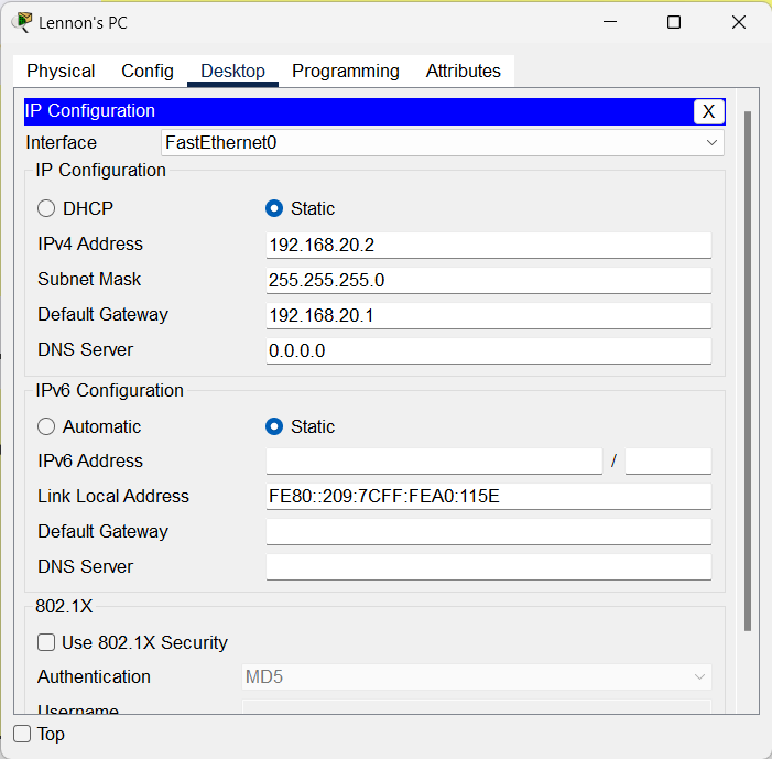
Step 2 (PC Configuration):
- Assign IP addresses to each computer in the network.
- Pick the Computer, navigate to the desktop, and then click IP Configuration, where you can provide an IP address, default gateway, and subnet mask.
- Set 192.168.10.1 as PC0’s default gateway.
- Assign 192.168.20.1 as PC1’s default gateway.

Step 3 (Connecting the Computers to the Router):
- Using a copper straight-through cable, connect Isaiah’s PC FastEthernet0 port to Router1’s GigabitEthernet0/0 port.
- Using a copper straight-through cable, connect Lennon’s PC FastEthernet0 port to Router1’s GigabitEthernet0/1 port.
NETWORK TOPOLOGY SAMPLE
Pinging PCs if they are connected each other